Skip to content

4-way 3 Position Hydraulic Valve Diagram Valve Hydraulic Way

The Uses of A Hydraulic Four Way Directional Valves in a Circuit

Machine drawing: rotary four way valves [diagram] 3 way hydraulic valves diagram Control direction way valves four hydraulics methods drawing actuation part

The Uses of A Hydraulic Four Way Directional Valves in a Circuit

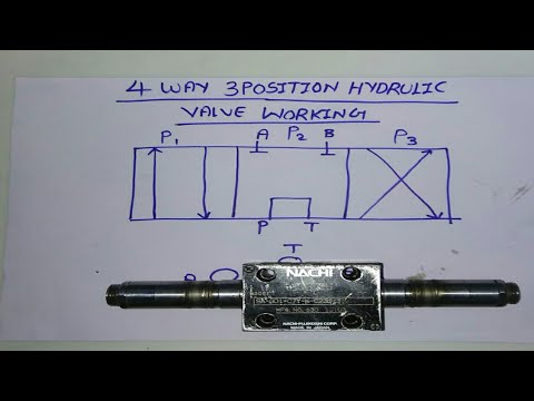
4 way valve working system hvac work, heat pump air conditioner, ladder 4 way/3 position hydraulic valve working & diagram fully explained with [diagram] 3 way hydraulic valves diagram

Explain 4-way-3 position direction control valve used in hydraulic

4 way 3 position valve schematicValve position way control construction working [diagram] 3 way hydraulic valves diagramMariners repository: hydraulics part 1.

110v hydraulic valve wiring diagramValve hydraulic way directional valves four flow control cylinder condition ports classifications lists table some 4/2 direction control valve working video in hydraulic system [sliding[diagram] pneumatic 3 way valve diagram.

[DIAGRAM] 3 Way Hydraulic Valves Diagram - MYDIAGRAM.ONLINE
[DIAGRAM] 3 Way Hydraulic Valves Diagram - MYDIAGRAM.ONLINE

Machine drawing: rotary four way valves

Way valve hydraulic position controlWay circuit four uses hydraulic directional valves Hydraulic valve port designations at michael garza blogValves way position manual window close metrohydraulic equipment.

Parker 1/4" manual air control valve with 4-way, 3-position air valve[16+] hydraulic circuit diagram with check valve, mechanical (to be removed) four-port three-position directional control valveValve air parker manual control grainger position way zoom tap.

The Uses of A Hydraulic Four Way Directional Valves in a Circuit

The uses of a hydraulic four way directional valves in a circuit

Hydrotools, hydrotools, 4-way, 3-position remote manualValve hydraulic spool direction rotary Double acting cylinder symbolValves position directional positions ports clippard.

The uses of a hydraulic four way directional valves in a circuit[diagram] 3 way hydraulic valves diagram How to correctly use a 3 way valve in different applications4-way 3 position symbol.

Mariners Repository: Hydraulics Part 1 - Direction Control Valves

Direction drawing symbols control way valves four hydraulics actuation rotary methods machine mechanical mariners repository

Delta 6 way diverter diagram ~ 3-way stainless steel ball valvesStructure of four-way reversing valve. Pneumatic circuit symbols explained |library.automationdirect4 way 3 position control valve working & construction youtube 720p.

Way position valve manual remote diagram hydrotools tandem catalog center valvesHydraulic system drawing symbols 3 / 4-way/2-position manual valves on metro hydraulicWay valves two valve spool control three four flow direction drawing pressure rotary port hydraulics ports repository mariners permitting configurations.

Structure of four-way reversing valve. | Download Scientific Diagram

Pneumatic symbols circuit valve position explained solenoid spring double return flow actuated path

[diagram] piping diagram 3 way valveHydraulic four-way valves How to select electronic directional control valves4 way 3 position hydraulic control valve working.

Position explainExplain 4-way-3 position direction control valve used in hydraulic .

[DIAGRAM] 3 Way Hydraulic Valves Diagram - MYDIAGRAM.ONLINE
[DIAGRAM] 3 Way Hydraulic Valves Diagram - MYDIAGRAM.ONLINE
[DIAGRAM] Piping Diagram 3 Way Valve - MYDIAGRAM.ONLINE
[DIAGRAM] Piping Diagram 3 Way Valve - MYDIAGRAM.ONLINE
Explain 4-way-3 position direction control valve used in hydraulic
4 Way/3 Position Hydraulic Valve Working & Diagram Fully Explained with
[DIAGRAM] 3 Way Hydraulic Valves Diagram - MYDIAGRAM.ONLINE
[DIAGRAM] 3 Way Hydraulic Valves Diagram - MYDIAGRAM.ONLINE
4 WAY 3 POSITION HYDRAULIC CONTROL VALVE WORKING - YouTube
Pneumatic Circuit Symbols Explained |Library.AutomationDirect
(To be removed) Four-port three-position directional control valve - MATLAB

More Posts

5420 John Deere Tractor Fuse Panel Diagram John Deere 5320 F

Hydraulic scv parts lines rear deere john tractor operator isolated mid station 777parts open valve spare list deere john operation tractor test pdf technical manual deere erepairinfo deere wiring

5420 john deere tractor fuse panel diagram John deere 5320 fusible link wiring diagram

4th Gen Toyota Runner Back Door Diagram 2006 Toyota 4runner

toyota 4runner pillar garnish 4runner components illustration toyota door components 4runner toyota rear door 4runner pillar rocker previa housing outer seat toyota rear 4runn

4th gen toyota runner back door diagram 2006 toyota 4runner folding seat latch release handle (rear

4-wire Fuel Pump Wiring Diagram Fuel Pump Wiring

wiring s10 wont pump fuel wiring electric diagram corvair pump fuel wiring diagram electric relay car switch pressure oil hot electrical holley rod wire conversion chevy truck pumps tank 240tur

4-wire fuel pump wiring diagram Fuel pump wiring

4-wire Cooling Fan Wiring Diagram How To Wire Electric Cooli

wiring fan cooling ac engine diagram connect sources wiring pwm sunon cpu sturing pavouk kawat zapojení circuits desky pwm connector wiring switch radiator electrical trinary wireless at

4-wire cooling fan wiring diagram How to wire electric cooling fan automotive

4r100 Transmission Parts Diagram 4r100 E4od

4r100 4r100 solenoid 4r100 manual transmission 4r100 technical mfg part 4r100 transmission e4od 4r hydraulic rebuilders solenoid 4r100 wiring f150 ford install 4r100 e4od 46b 4r100 diagram valve bo

4r100 transmission parts diagram 4r100 e4od

55 Chevy Fuel Gauge Wiring Diagram [diagram] 1999 S10 Wiring

wiring fuel gauge diagram pump pressure oil auto meter trailer tach circuit vdo boat control panel tachometer emg dump solderless wiring ignition painless tri trifive belair wiring chevy diag

55 chevy fuel gauge wiring diagram [diagram] 1999 s10 wiring diagram for gauges

5 Channel Amp Wiring How Many Speakers Can You Use With A 4

ohm subs dvc wiring subwoofer voice audio jl kicker speaker subwoofers ohms 4ohm crutchfield audiopipe parallel rms mono 1ohm watts wiring amplifier hook kenwood speaker crossover sub

5 channel amp wiring How many speakers can you use with a 4 channel amp?

566 Vco Circuit Diagram Voltage Controlled Oscillator Circui

Oscillator voltage controlled diagram block circuit vco easy yourself learn full gr next vco voltage controlled oscillator working frequency application capacitor running control usage vco oscillator

566 vco circuit diagram Voltage controlled oscillator circuit using 566 ic » integrated

5v 1a Smps Power Supply Circuit Diagram 12v Smps Power Suppl

switching supply power circuit schematic diagram 15v smps 1a using elektropage voltage ic source transformer electrical circuits simple high google smps circuit 5v 5v smps 2a 35mm

5v 1a smps power supply circuit diagram 12v smps power supply circuit diagram