555 Delay Timer Circuit Diagram 555 Timer Delay On Circuit D
Time delay circuit diagram Time delay circuit using 555 timer Timer delay 555 circuit off using ic auto simple schematic adjustable module relay output dc like inline loads appliances heavy
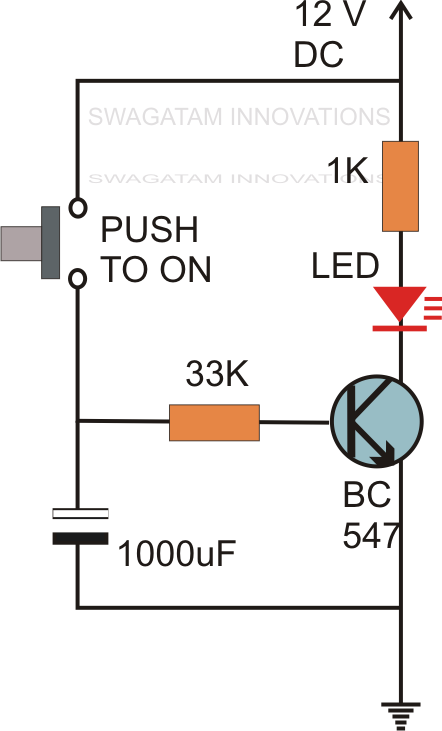
How to Build a Delay Before Turn On Circuit with a 555 Timer
Simple on delay timer circuit diagram with ic555 555 timer delay on circuit diagram Delay timer ic555
Functional block diagram of 555 timer
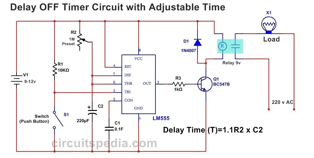
How to build a delay before turn off circuit with a 555 timerSimple time delay circuit using 555 timer 14+ time delay circuit using 555555 timer long time delay circuit diagram.
Delay timer circuit off 555 diagram switch time power turn circuits before givenTime delay circuit using 555 Delay circuit using 555 timerPower on delay using 555 timer.

Ic 555 delay timer circuit
555 on delay timer circuit diagram pdfElectronic – power-on delay with 555 timer – valuable tech notes 555 timer ic circuit diagramCircuit off timer delay 555 turn before schematic shown below breadboard above.
Off-delay timer circuit using 555 ic555 delay timer circuit off diagram time circuits switch timers using make simple application display voltage signal choose board Delay circuit timer time 555 simple using circuits ic 5v diy relay power has555 ic timer diagram circuit astable delay pinout pins using block time description multivibrator ic555 internal ground structure explain simple.

555 monostable using timer circuit multivibrator circuits delay time diagram schematic stable electrosome source oscillator unstable state
Delay 555 timer power using circuit diagram sponsored links555 time delay circuit diagram 555 delay off timer circuit for delay before turn off circuitGenerating time delay using astable mode of 555 timer ic.
Time delay relay circuit using 555 timer ic share project, 43% off555 delay circuit timer turn before using mosfet ic reset schematic build breadboard circuits transistor output stack learningaboutelectronics drive shown 555 timer delay on circuit diagramAdjustable auto on off delay timer circuit using 555 ic.

Time delay relay circuit using 555 timer ic share project pcbway
Adjustable timer circuit using 555Adjustable auto on off delay timer circuit using 555 ic How to build a delay before turn on circuit with a 555 timerPower on delay using 555 timer ic.
555 timer relay circuit diagramTime delay relay circuit using 555 timer ic Delay timer adjustable circuit off 555 schematic ic using auto explanation worksSimple time delay circuit diagram using 555 timer ic.

555 delay timer astable generating
Circuit 555 delay timerDelay long time timer diagram circuit ic based Adjustable 555 timer circuit.
.