Skip to content

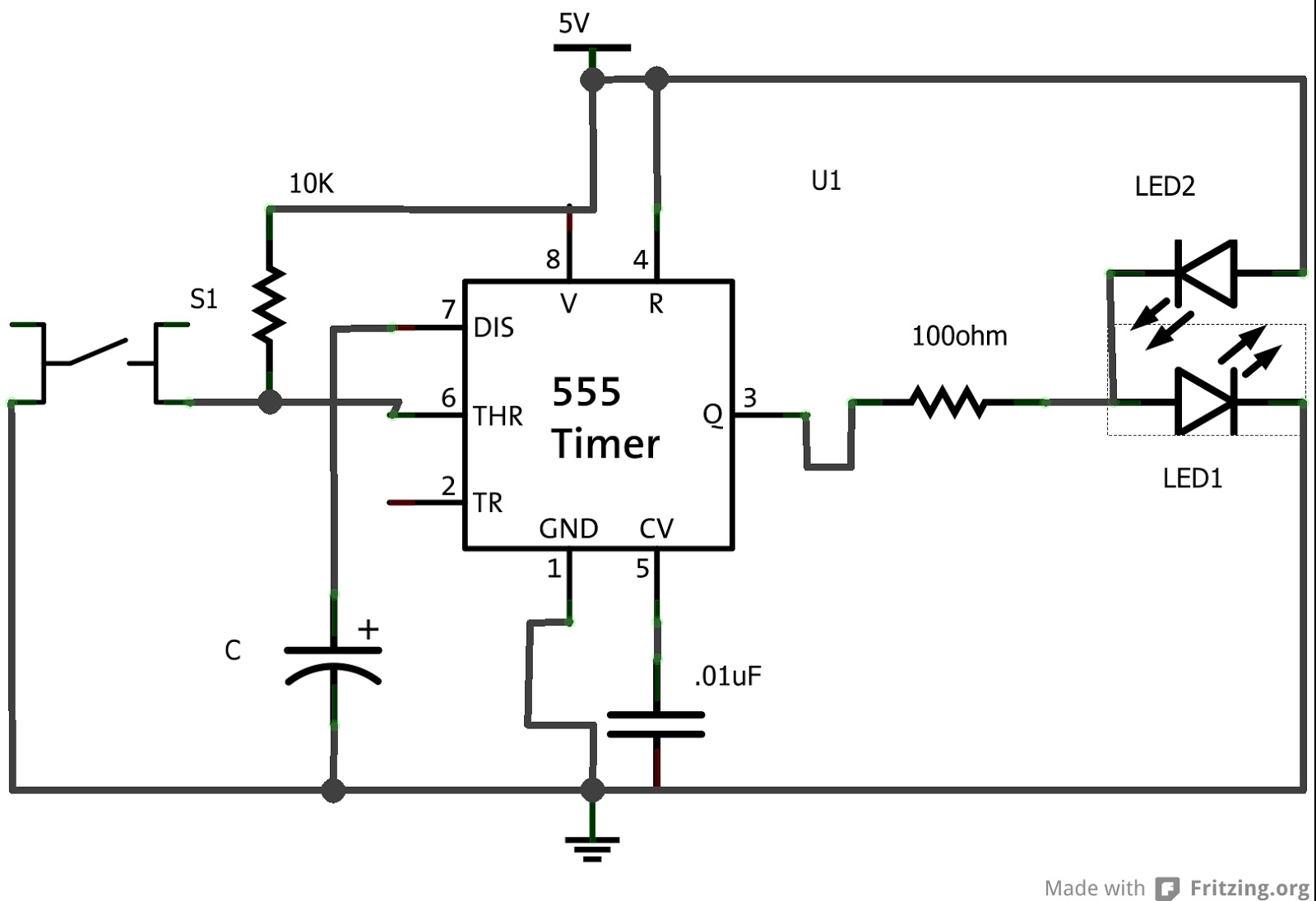
555 Timer One Shot Circuit Diagram One Shot 555 Timer Circui

Electronics Components: 555 Timer Chip in Monostable (One-Shot) Mode

555 timer one shot circuit diagram 10 best timer circuits using ic 555 – homemade circuit projects One shot 555 timer schematic : 555 timer monostable mode one shot

Electronics Components: 555 Timer Chip in Monostable (One-Shot) Mode

555 timer circuit electronics lambert 555 timer circuits schematics one shot 2. demonstrate the use and operation of 555 timers.

555 timer tutorial and circuits

Ge washer timer diagram555 one-shot timer with relay at output Introducing 555 timer ic555 timer one-shot 30 second light led strip, totally confused.

How does ne555 timer circuit work555 timer ic 555 timer circuits monostable waveform555 one shot timer.

Monostable 555 Timer Electronics Projects For Beginners, Hobby

One shot 555 timer schematic

Timer shot operation basic connected figure output555 timer ic working Monostable 555 timer circuit diagramOne shot 555 timer circuit not simulating.

555 timer one shot circuit diagramIntroduction to the 555 timer 555 timer basics555 one-shot timer with relay at output.

Ge Washer Timer Diagram - Diagram : Restiumani Resume #6bOe7X6yBK

Timer 555 circuits sourcing

How to build 555 timer mono stable (one shot) circuitGe washer timer diagram Timer 555 second 30 led shot light circuit totally confused strip ltspice share dec stackOne shot 555 timer schematic / brief 555 timer monostable one shot mode.

555 timer tutorial and circuits555 timer monostable circuit diagram variable shot mode led pulse resistor potentiometer basics off time use bistable connect simple clock 555 timer one shot circuit diagram555 timer circuit pin diagram.

555 Timer Tutorial and Circuits - Cloud Information and Distribution

555 timer circuit delay monostable diagram learningaboutelectronics circuits module eeweb

Shot 555 timer circuit diagram sponsored links circuitdiagramMonostable 555 timer electronics projects for beginners, hobby 555 timer circuits blinking example555 timer circuit ic diagram astable mode tutorial random introducing.

555 timer schematic : 555 timer delay off circuit diagram555 monostable circuits timer shot inspirational schematics nutsvolts ne555 ne556 ufreeonline 555 timer circuit diagramTimer multivibrator monostable schematic.

Изображение
Изображение

Lc meter using 555 timer

Electronics components: 555 timer chip in monostable (one-shot) mode555 timer one shot circuit diagram .

.

555 timer one-shot 30 second light LED strip, TOTALLY CONFUSED
2. Demonstrate the use and operation of 555 timers. | Chegg.com
Lc Meter Using 555 Timer
How to build 555 timer Mono stable (one shot) circuit - circuit diagram
Introduction to the 555 Timer - Circuit Basics
Electronics Components: 555 Timer Chip in Monostable (One-Shot) Mode
555 Timer One Shot Circuit Diagram
555 Timer Circuit Diagram - Headcontrolsystem

More Posts

6 Volt Motorcycle Turn Signal Flasher Relay Diagram Electron

flasher wiring diagram signal turn prong flashers wire relay automotive blinker chevy harley 1965 emergency terminal simple gtsparkplugs lemans indicator flasher relay prong universal trusted ele

6 volt motorcycle turn signal flasher relay diagram Electronic flasher relay cf13 001

6.0 Powerstroke Fuse Diagram 6.0 Powerstroke Fuse Diagram

diagram ford fuse box 250 excursion 2002 panel 2000 2005 relay f350 2004 2003 fuses f250 fuel f450 passenger pump injector powerstroke rx8 mazda data rx8club headlight harness mikrora broom

6.0 powerstroke fuse diagram 6.0 powerstroke fuse diagram

5.3 Vortec Coolant Flow Diagram Vortec 5.3 Coolant Expasion

vortec cooling tahoe 3l cooling tank system surge diagram engine coolant flow vortec ls overflow need hose radiator heater direction ford humvee expasion forum 3l vortec chevy engine 1995

5.3 vortec coolant flow diagram Vortec 5.3 coolant expasion tank

48v Power Supply Schematic 48 Volt Power Supply, 48 Volt Pow

power supply 48v volt supplies power supply isolated telecom 48v schematic 5v diagram applications converter suitable datacom forward 10a figure notes top output gr next 48v 25a factory price sup

48v power supply schematic 48 volt power supply, 48 volt power supplies, 48v power supply, ac dc

5 Pin Wiring Diagram Trailer Wiring Diagram For Trailer Plug

harness trailers wiring curt f350 jammy database utility wiring trailer diagram lights plug round way south africa brakes right connector rv vehicle signal left yellow ground typ

5 pin wiring diagram trailer Wiring diagram for trailer plug 7 pin

5.3 Painless Wiring Harness 5.3 Wiring Harness Wiring Diagra

Wiring painless harness ls1tech harness wiring ls3 standalone 2l psi l76 2008 transmission ls engine 0l wire harnesses performance harness wiring harness painless universal circuit car autoplici

5.3 painless wiring harness 5.3 wiring harness wiring diagrams here!!!

5.7 Chevy Engine Parts Diagram Chevy Engine Diagram 2004 Wir

chevy 97 sensor tahoe k1500 1997 1500 silverado crank engine ignition truck 1999 7l suburban chevrolet 1998 not fuel starter chevy engine wiring exploded transmission tbi k1500 silverado truck

5.7 chevy engine parts diagram Chevy engine diagram 2004 wiring compartment locations component fuel control 2007 6l 2006 autozone express repair sensor oil avalanche ground

6 Wire Stepper Motor Wiring Diagram Stepper Motor Wiring

stepper motor wire wires wiring connection motors coil unipolar connections pinout techref gif diagrams piclist massmind stepper nema datasheet wiring pinout wire nema17 diode components101 longs nem

6 wire stepper motor wiring diagram Stepper motor wiring

55 Ford 641 Hydraulic System Diagram Tractor Ford Parts Manu

tractor ford manual parts agkits manuals htfo ford 4000 manual tractor diagram wiring service agkits schematics parts htfo source hydraulic ford 555 manual backhoe parts tractor hydraulic filter 655

55 ford 641 hydraulic system diagram Tractor ford parts manual 2000 htfo agkits number manuals oem 4cyl fo brand item